3D Scanning and Printing
For this week's assignment,
• Individual assignment 1: design and 3D print an object (small, few cm) that could not be made subtractively
• Individual assignment 2: 3D scan an object
3D Printing
3D printing is an additive process of creation. Not unlike an inkjet printer, a printer head draws a slightly extruded image, steps up one level, draws another, another, and so on until a 3D thing is formed.
In our lab (Fablab Kochi) We have been using Ultimaker for 3D printing. It's very easy to use
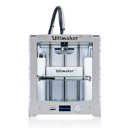
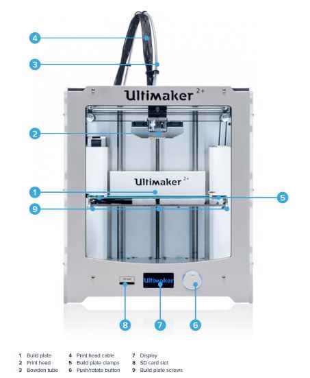
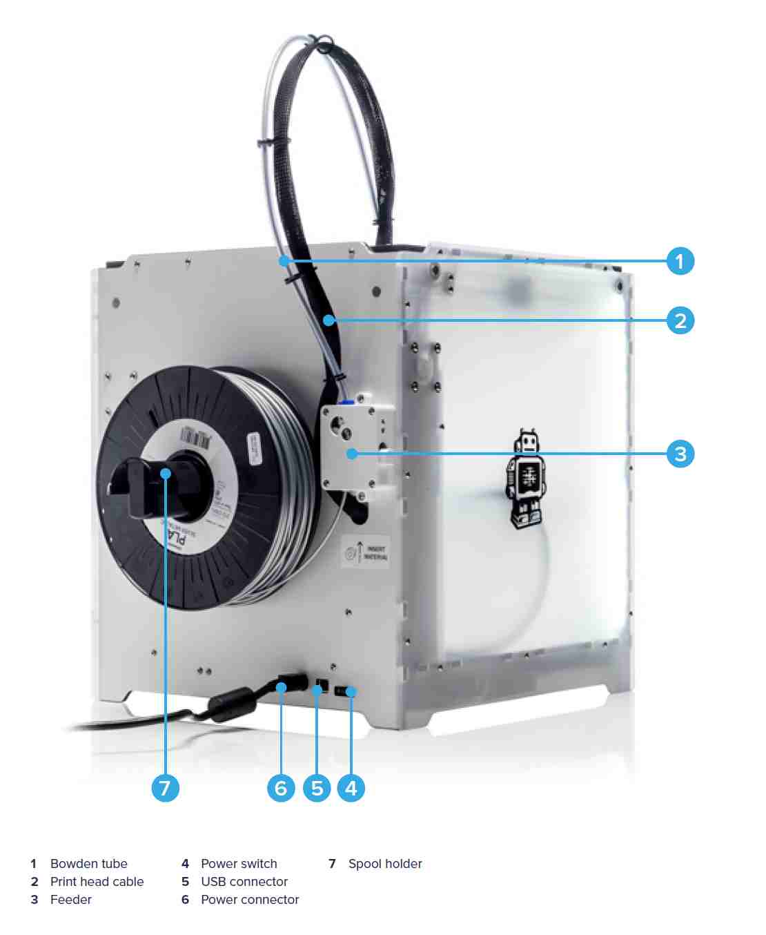
Ultimaker 2+
Front
Back
All the following test are made with our Ultimaker 2+ 3D-Printer. So let’s start with the first test
Before I started with the final work, I did my own test print. This is useful to take a look at the calibration and if everything works well.
Group Assignment
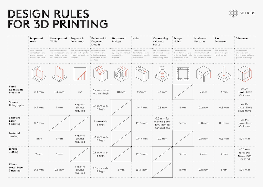
design rule
Different 3D printing processes have different capabilities and different design restrictions. In this article we will talk about key design considerations that apply to all 3D printing processes.
I got a set of tests for checking the design rules. Luckly I find a full set of test from Thingverse

Rafts
- Yes
Supports:
- No
Resolution:
-0.1mm or higher
Infill:
30%
Parameters
01 Nut, Size M4 Nut should fit perfectly
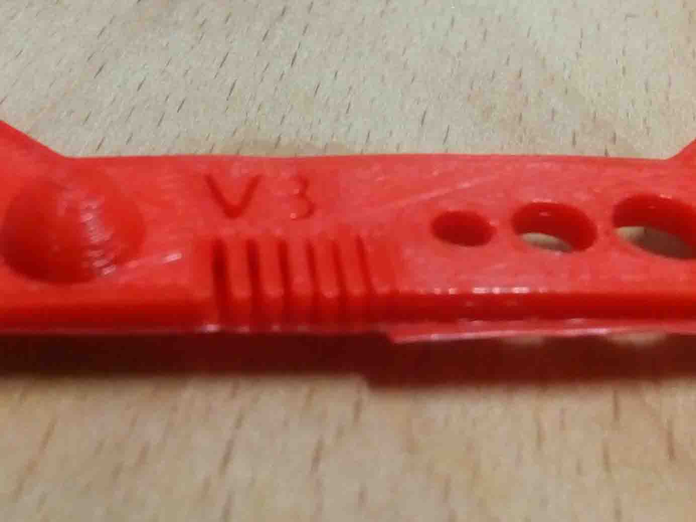
02 Wave, rounded print
03 Star, Sharp Edges
04 Name, Complex Shapes
05 Holes, Size 3, 4, 5 mm
06 minimal Distance: 0.1, 0.2, 0.3, 0.4, 0.5, 0.6, 0.7 mm
07 Z height: 0.1, 0.2, 0.3, 0.4, 0.5, 0.6, 0.7, 0.8, 0.9, 1.0, 1.1 mm
08 Wall Thickness: 0.1, 0.2, 0.3, 0.4, 0.5, 0.6, 0.7 mm
09 Bridge Print: 2, 4, 8, 16 mm
10 Sphere, Rounded Print 4.8mm height
11 Sphere Mix, 7 mm height
12 Pyramide, 7 mm height
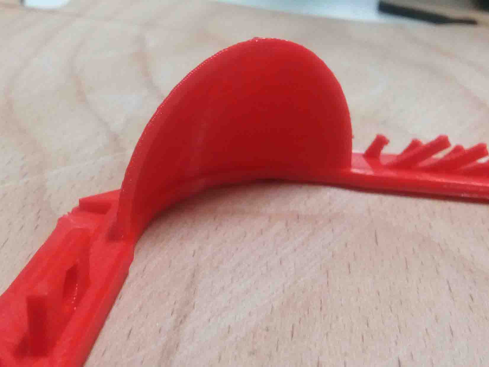
13 Overhang: 25, 30, 35, 40, 45, 50, 55, 60, 65, 70°
14 Warp, does it bend?
15 3D Print Font, optimized for 3D printing
16 Surface, Flatness
17 Size, 100 x 100mm x 23.83 (10mm width)
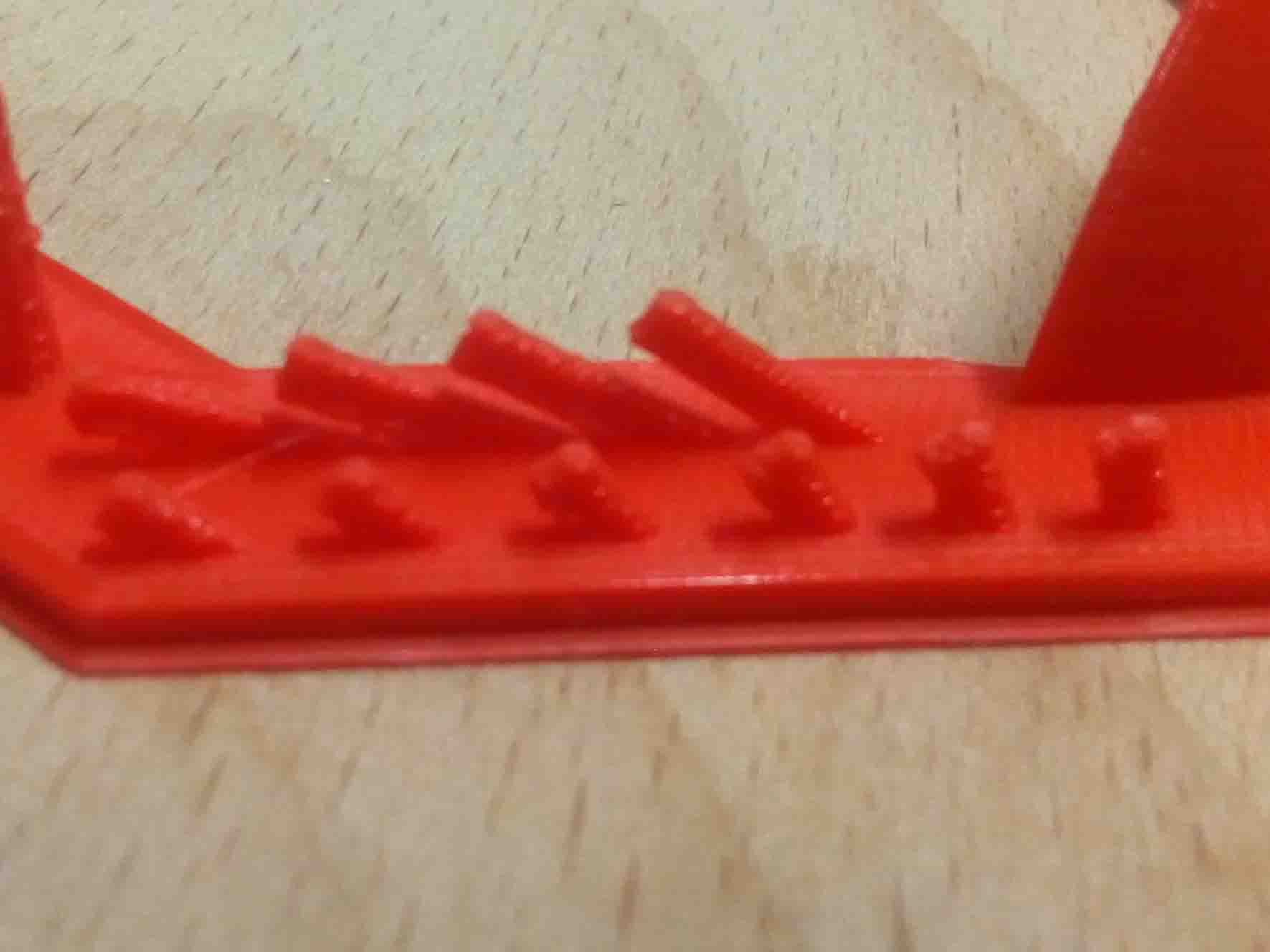
18 Spike, minimum Layer Time, 21 mm height from Bottom (include Baseplate)
19 Hole in Wall, 4 mm diameter, check for proper print
20 Raft Test, raft should be just under the model
21 Retract Travel, check retract settings for longer travel
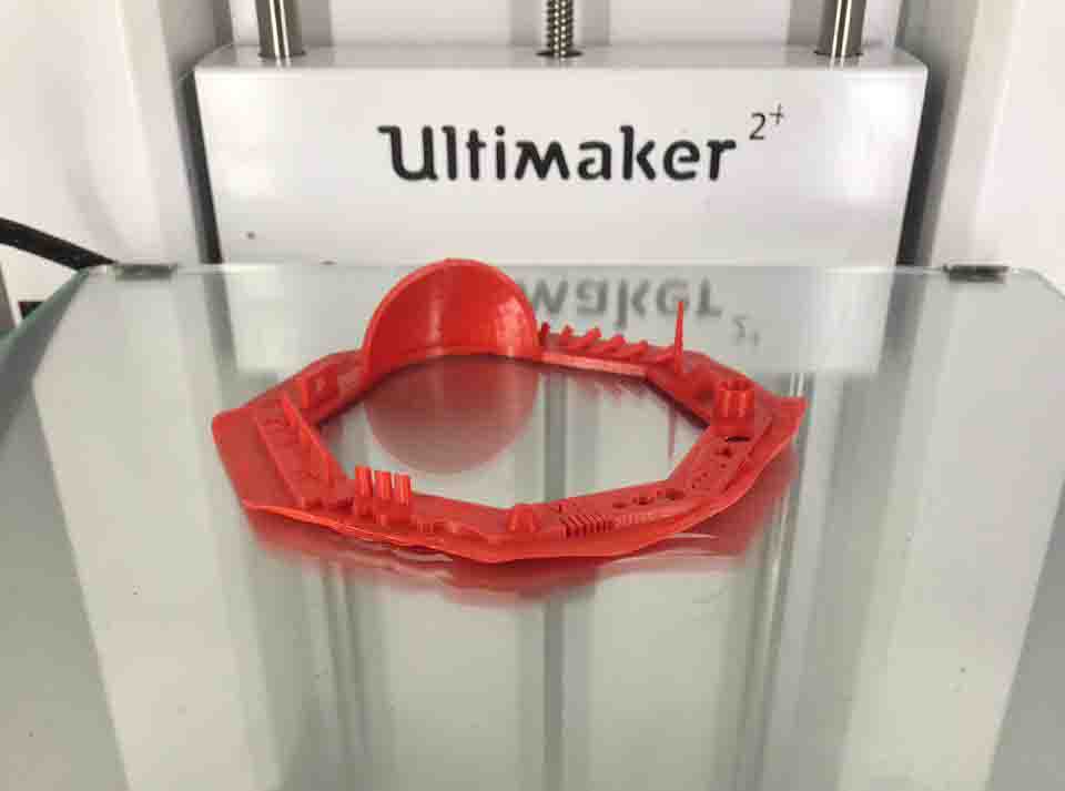
We follow the instructions and put it to print
Digital vs. Physical
The most important thing to remember while designing for 3D printing is the fact that your digital design will become a physical object. In the digital design environment, there are no laws of physics to adhere to, such as gravity.Each 3D printing process has its own limitations. Here are the most important design considerations that apply to all of them that you should keep in mind:
General Design Consideration for 3D Printing
Overhangs
All 3D printing processes build parts layer-by-layer. Material cannot be deposited onto thin air, so every layer must be printed over some underline material. Overhangs are areas of a model that are either partially supported by the layer below or not supported at all. There is a limit on the angle every printer can produce without the need of support material. For example, for FDM and SLA this angle is approximately 45o degrees. It is a good practice to limit the overhangs of a model, as layers printed over support usually have a rougher surface finish.
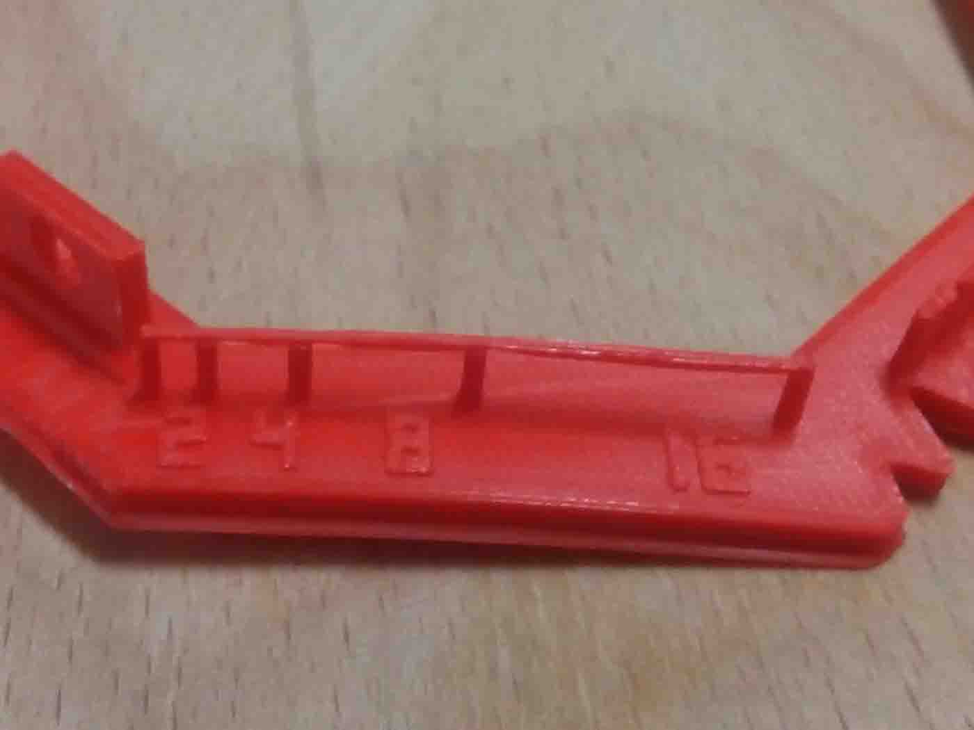
Wall thickness
The second thing to keep in mind when designing a part to be 3D printed is wall thickness. Every 3D printing process can produce accurately features that are thin up to a certain point. For example, imagine you are an engineer who designs hang gliders for a living. You have come up with a great, new design that you have decided to 3D print scaled down for testing. 3D modeling programs allow you to model the sailcloth of the wing, but you would encounter problems when you would try to 3D print it, as its thickness would be extremely small. As a good practice, always add thickness to your models. Walls with thickness greater than 0.8 mm can be printed successfully with all processes.
Warping
Something that is often easily overlooked while designing a 3D model is the fact that the materials used for 3D printing undertake physical change: they are melted, sintered or scanned with a laser and solidified. The heating and cooling of material can cause the parts to warp while printing. Large, flat surfaces can be especially prone to warping. Warping can typically be avoided by using correct machine calibration and having adequate surface adhesion between your part and the print bed. Your Hub will be able to offer more advice on design techniques that can be used to minimize the likelihood of warping. A good practice is to avoid large flat surfaces and add rounded corners to your 3D models.
Level of detail
When you are creating a 3D model with intricate details, it is important to keep in mind what is the minimum feature size each 3D printing process can produce. The minimum level of detail is connected to the capabilities and mechanics of each 3D printing process and to the selected layer height. The process and materials used will have an impact on the speed and cost of your print, so determining whether smaller details are critical to your model is an important design decision.
3D Designing
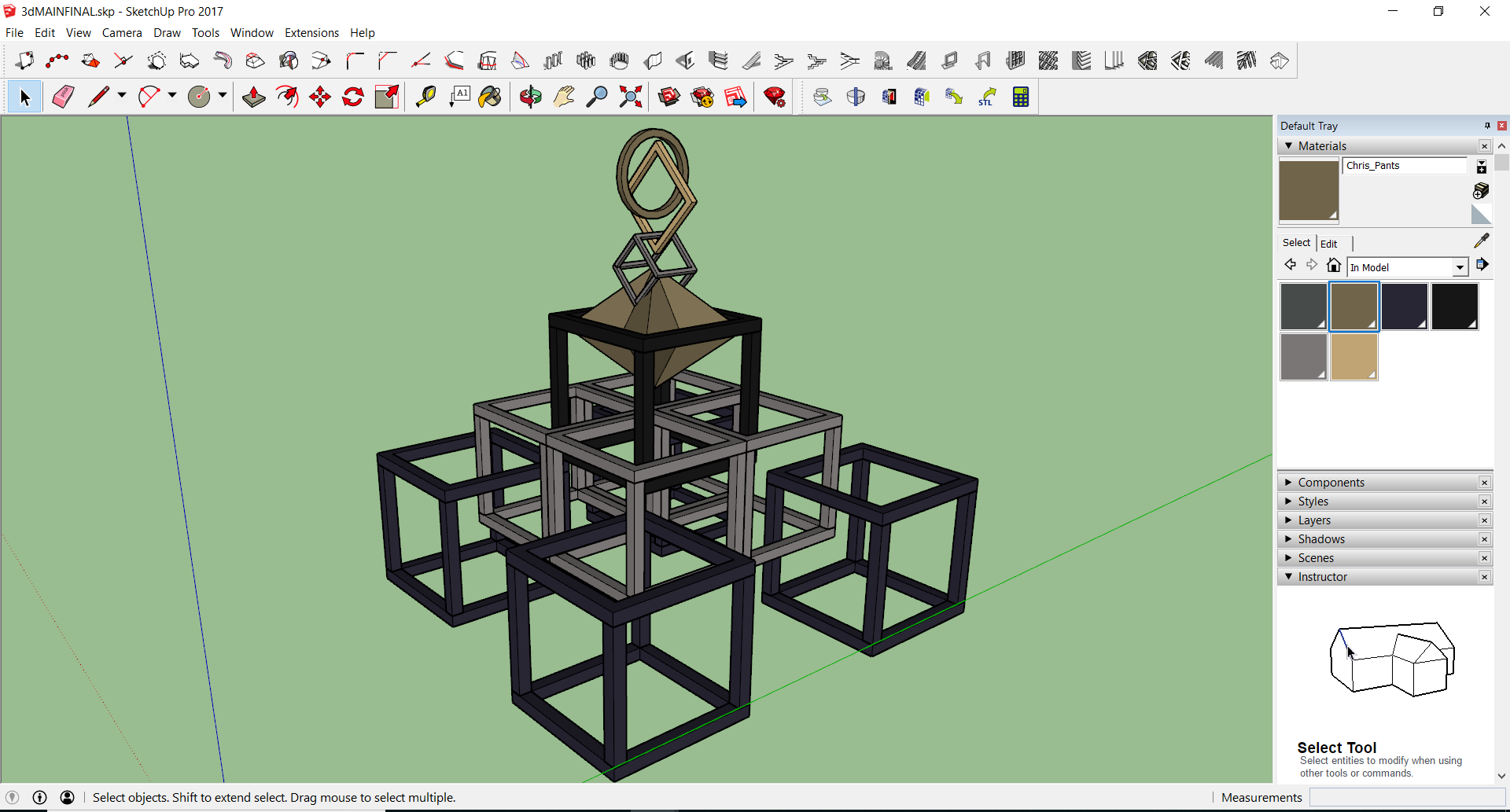
For this process, I use sketch up 2017 to make the design. Using sketch up was more flexible for me. I could really reduce the design complexity by using a simple software. A basic cube model was designed in sketch up and multiple copy of it was used to develop a design.
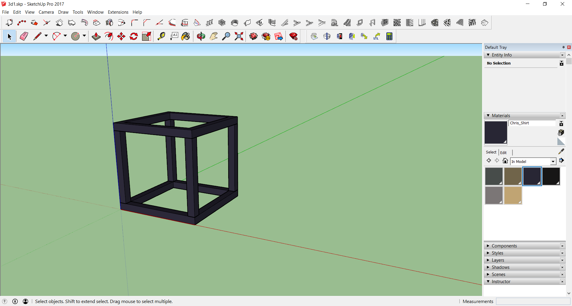
By interlocking the cubes in different position I could achieve a simple design. First I tried out a simple 3 cube interlocking test print.
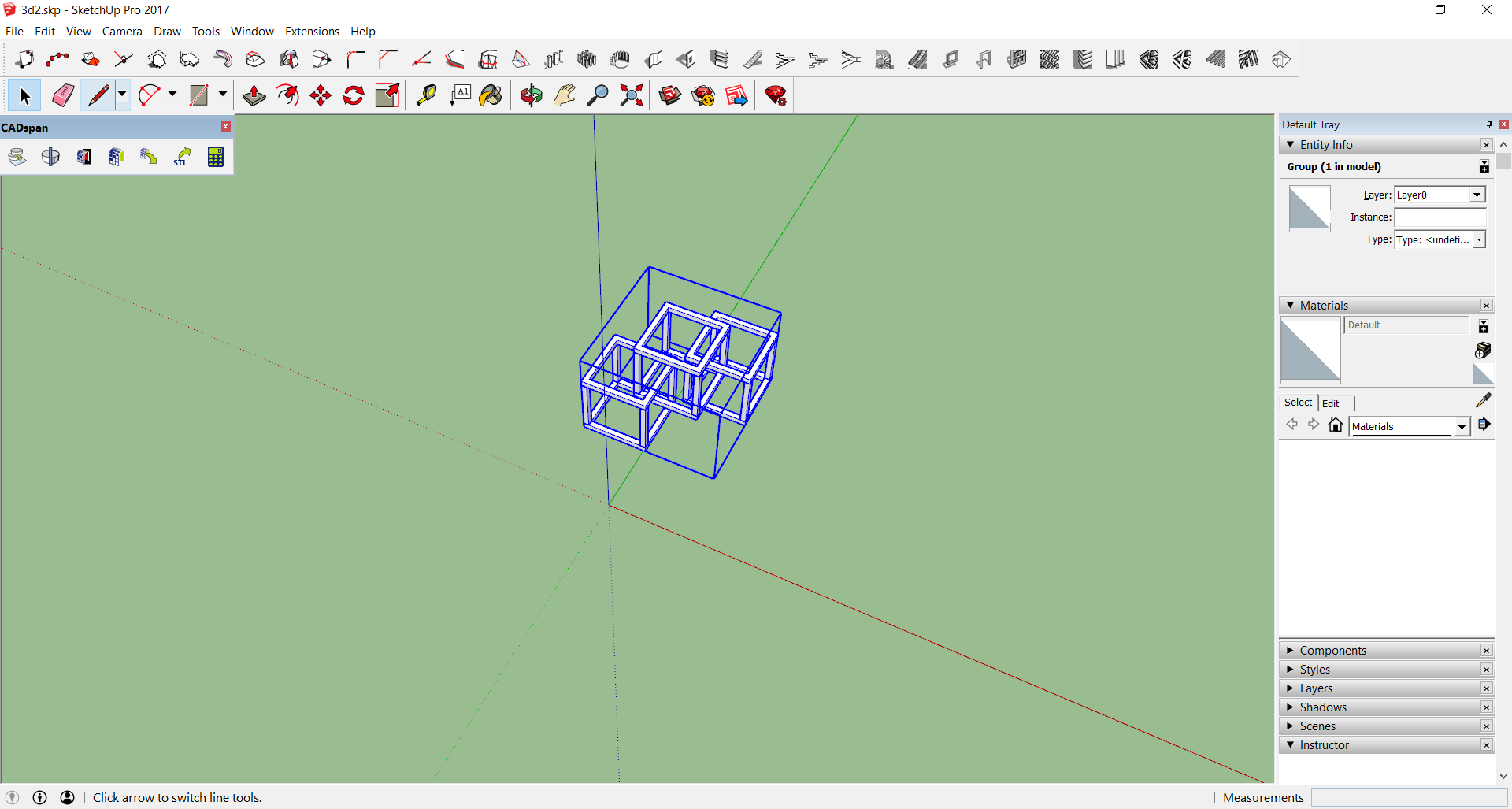
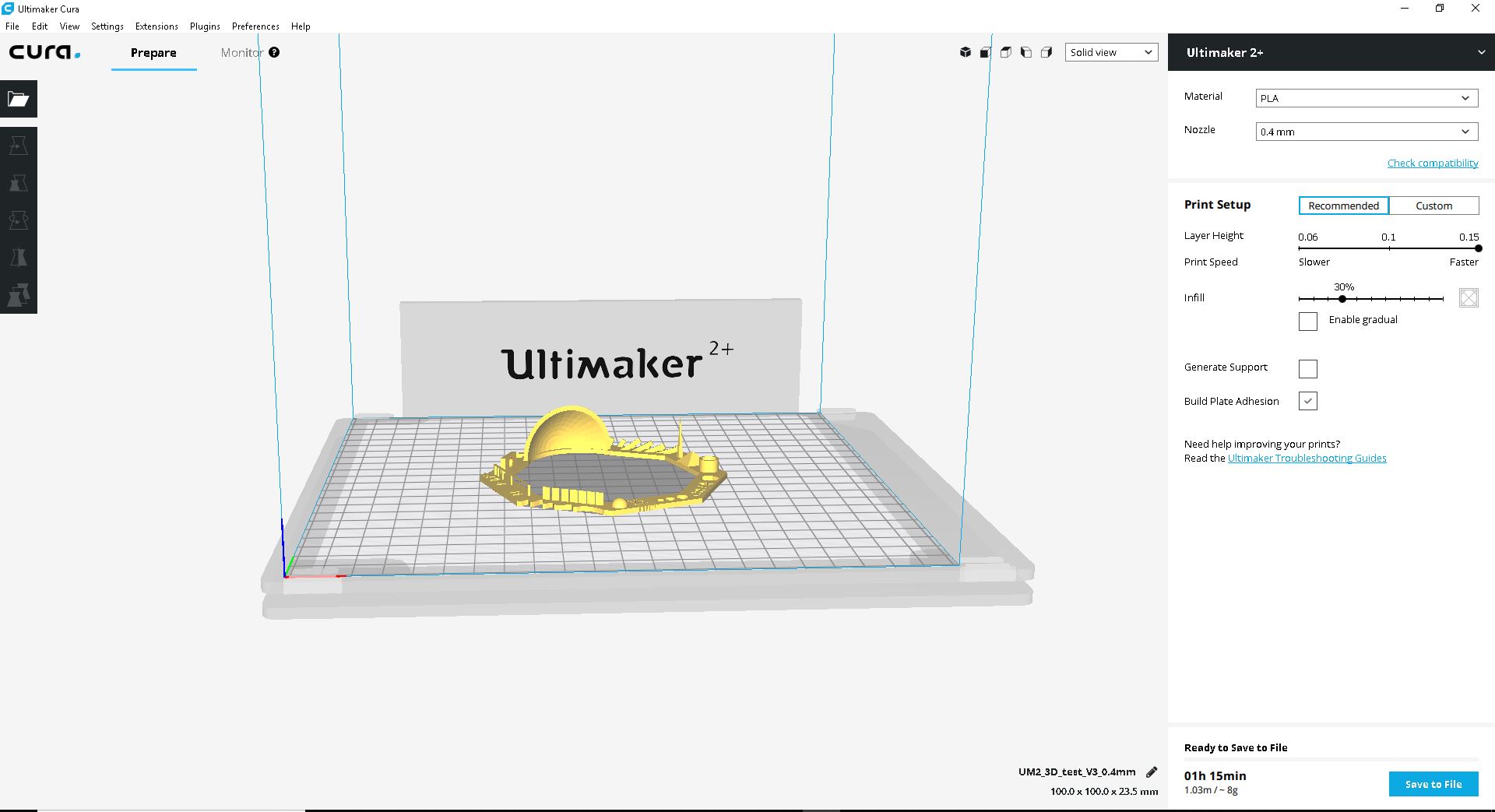
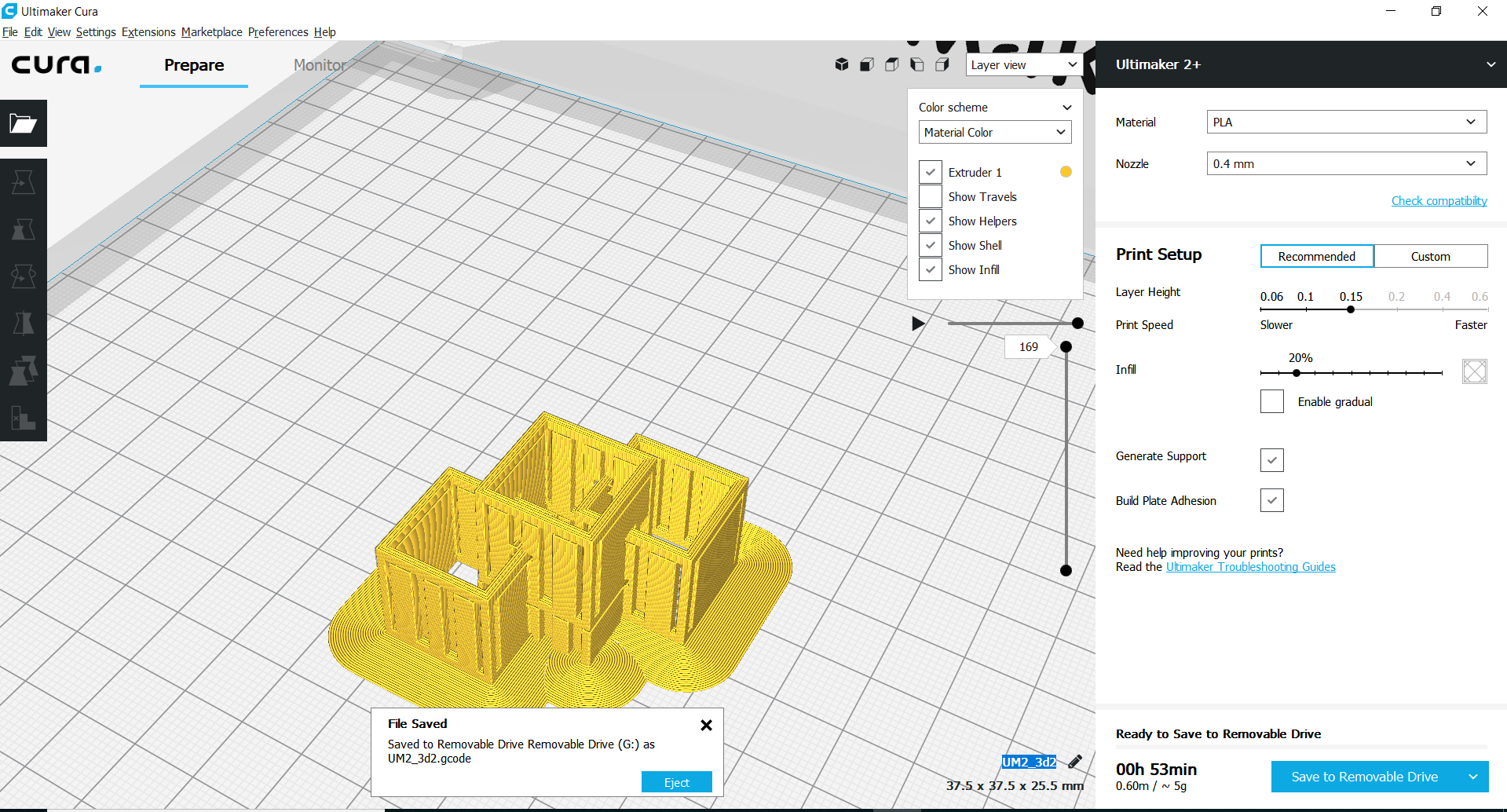
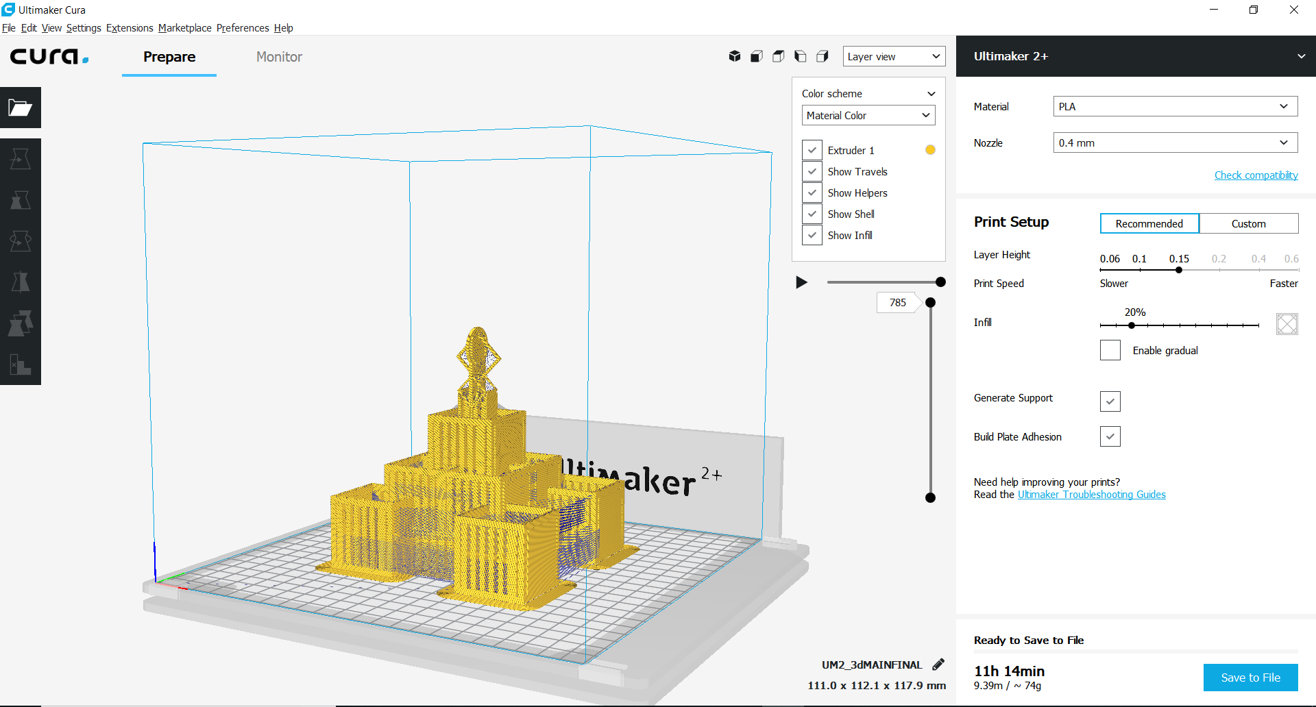
All this modelling saved in STL format and Cura software used to generate the print files.
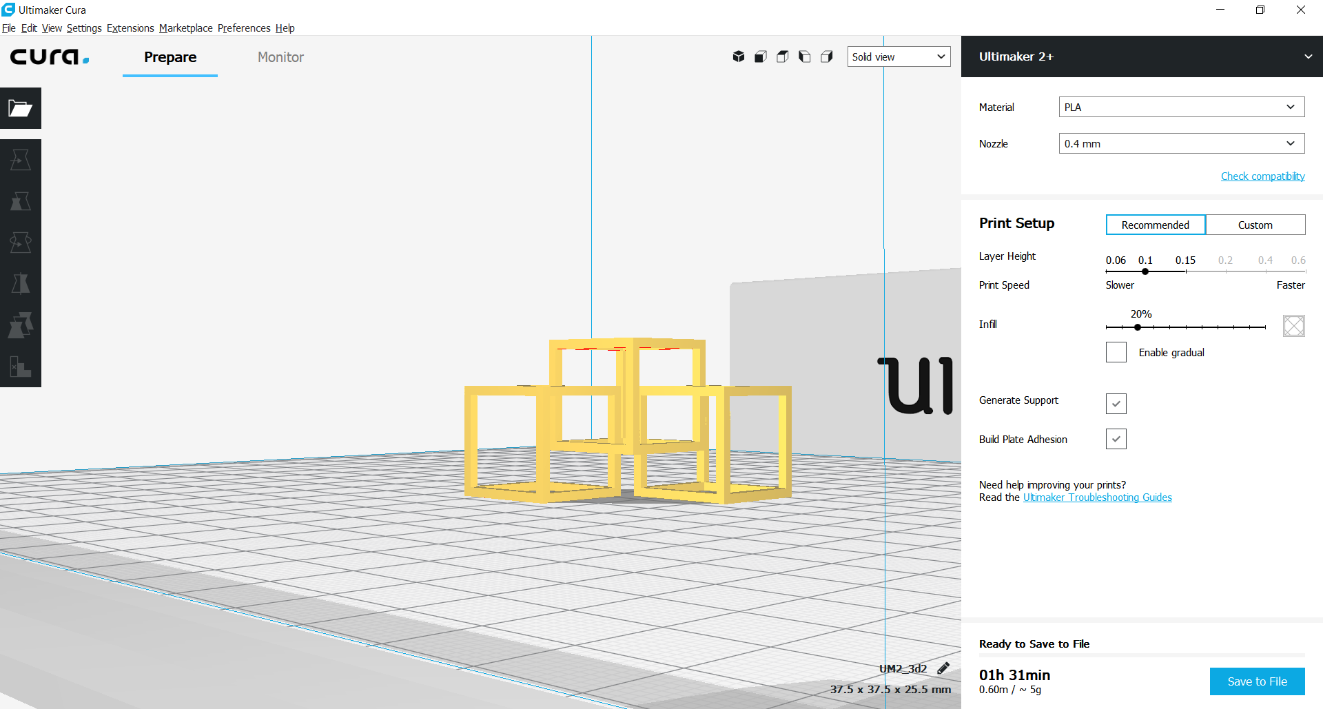
In the next step I used the ultimaker software cura to set the correct setting. See the setting below. Notice the missing point at “Generate Support”. try to generate a support (red surface).
As you see the result is with the chosen settings very good. The only problem we face during the printing is that, there is no natural support so if there is too high angle of the overhang you need to generate a support structure which should be removed after the print. This decreases the surface quality. Removing the support structures can cause destruction to the original portion. I tried to remove the supporting structures carefully still I faced join breaks in my test piece. Therefore the main challenge is to remove the excess without surface problems
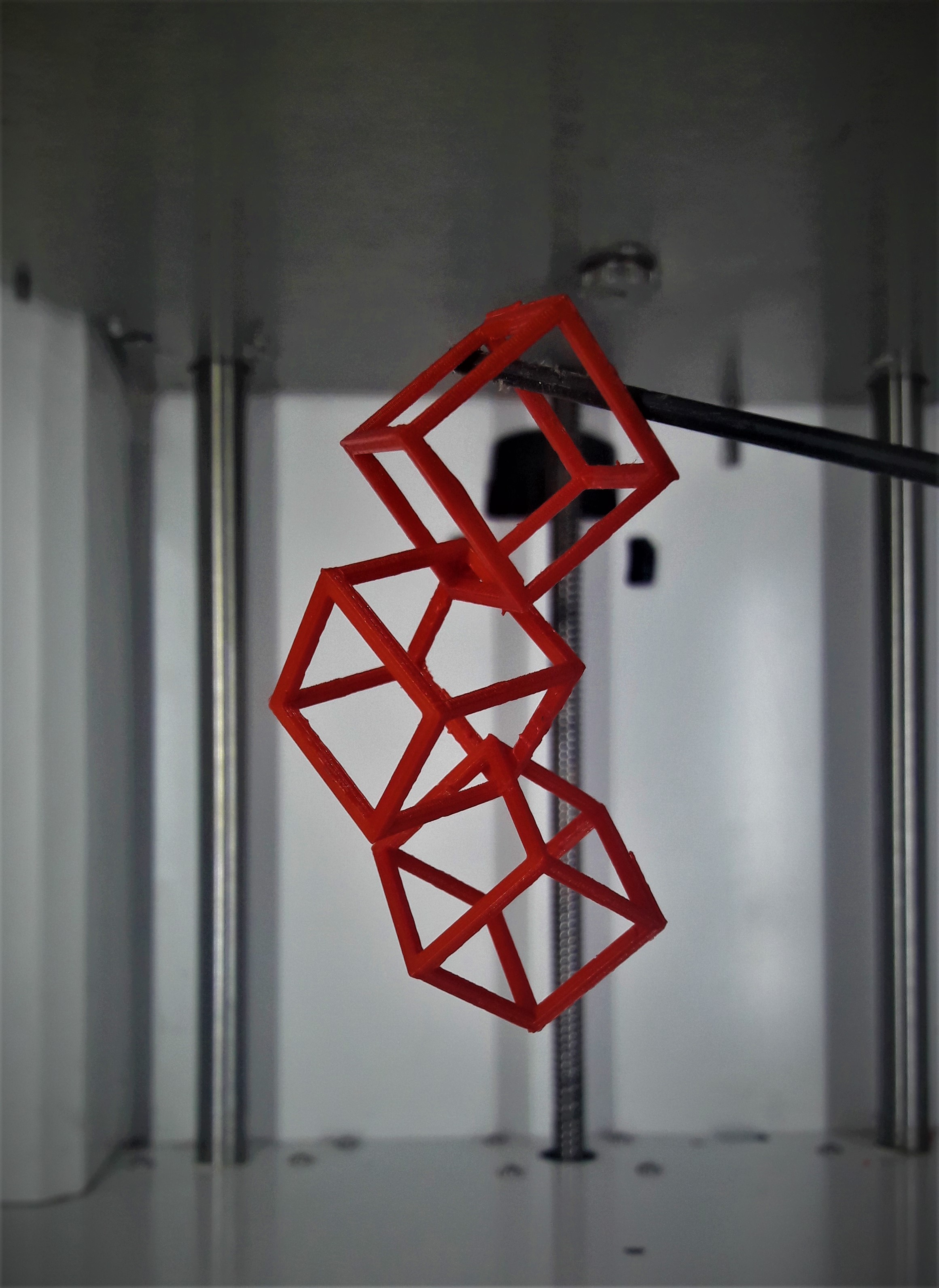
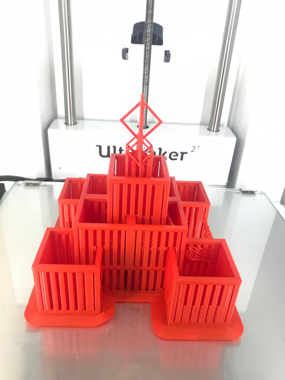
The test print looks quite good. The interlocking has been printed like excepted.
Printing
So now we are physicaly printing the design using an Ultimaker 3d printer. For that we need insert the SD card into the SD card slot in the Ultimaker.
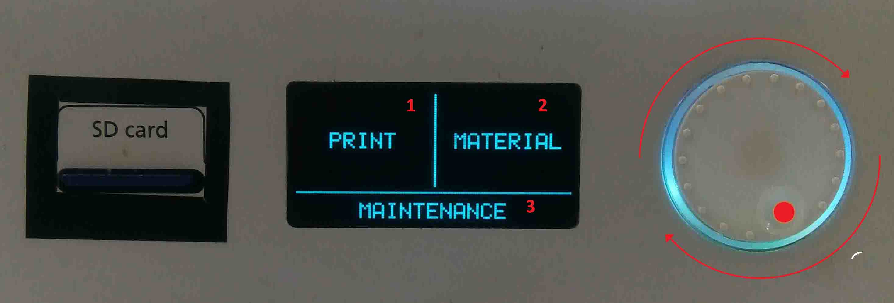
In the display, There are three options:
Print
Material
Maintenance
Here we can select each options using the "push-rotate" button. Now we need to give the print command using the push rotate button.
Select and press "Print"
Select file
Wait for the bed to heat
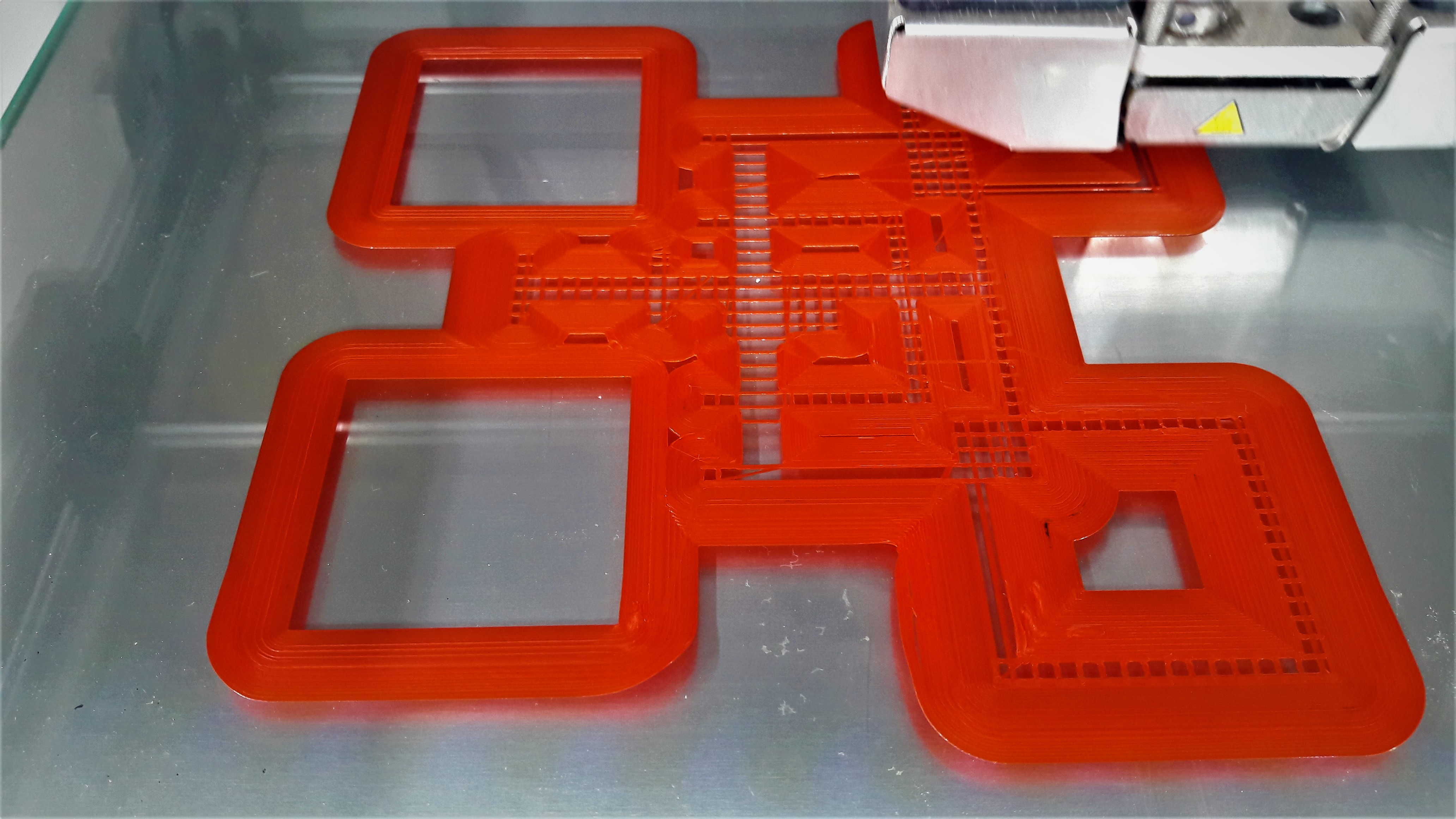
The printed structure initially looked like this.
You can download the file here.
HERO SHOT
3D Scanning
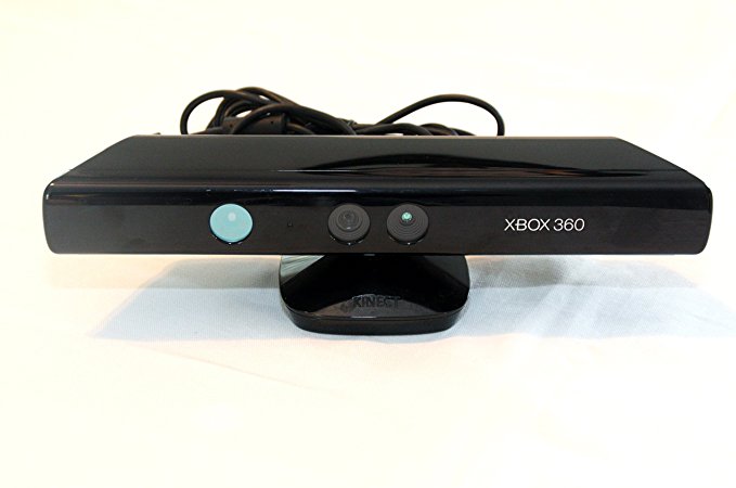
Microsoft Kinect
Kinect is Microsoft’s motion sensor add-on for the Xbox 360 gaming console. The device provides a natural user interface (NUI) that allows users to interact intuitively and without any intermediary device, such as a controller.
The Kinect system identifies individual players through face recognition and voice recognition. A depth camera, which “sees” in 3-D, creates a skeleton image of a player and a motion sensor detects their movements. Speech recognition software allows the system to understand spoken commands and gesture recognition enables the tracking of player movements. Although Kinect was developed for playing games, the technology has been applied to real-world applications as diverse as digital signage, virtual shopping, education, telehealth service delivery ,Robotics ,3D mapping etc
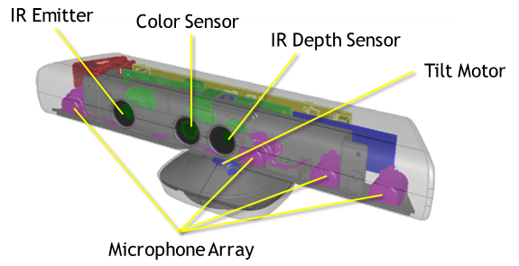
There's a trio of hardware innovations working together within the Kinect sensor:
Color VGA video camera
This video camera aids in facial recognition and other detection features by detecting three color components: red, green and blue. Microsoft calls this an "RGB camera" referring to the color components it detects.
Depth sensor
An infrared projector and a monochrome CMOS (complimentary metal-oxide semiconductor) sensor work together to "see" the room in 3-D regardless of the lighting conditions.
Multi-array microphone
This is an array of four microphones that can isolate the voices of the players from the noise in the room. This allows the player to be a few feet away from the microphone and still use voice controls.
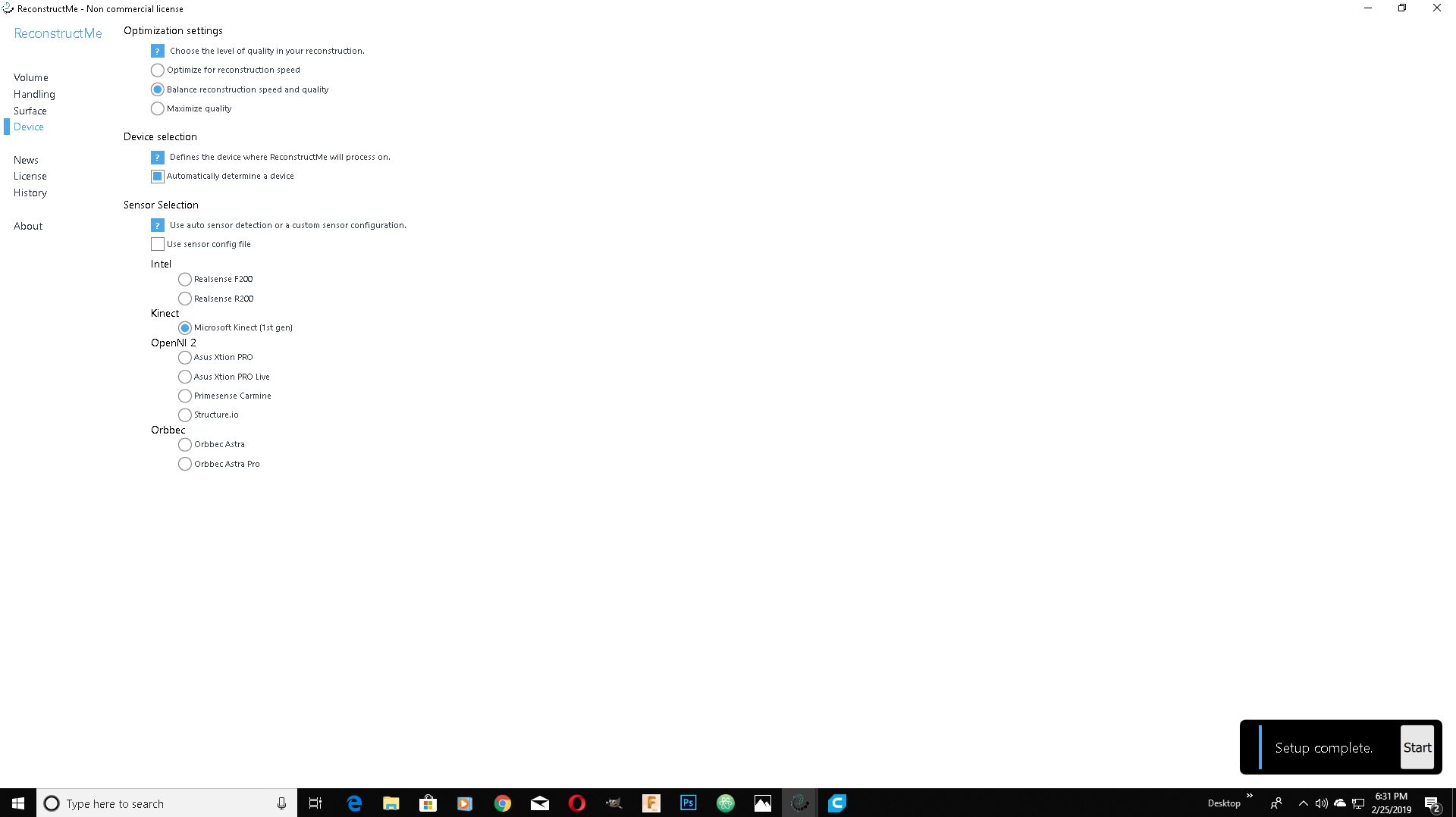
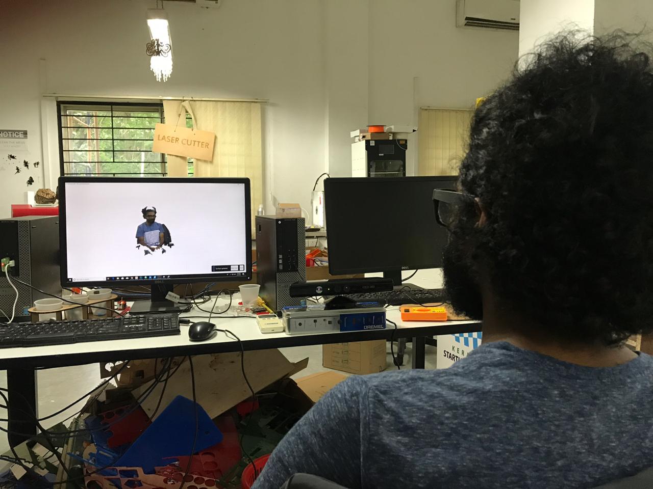
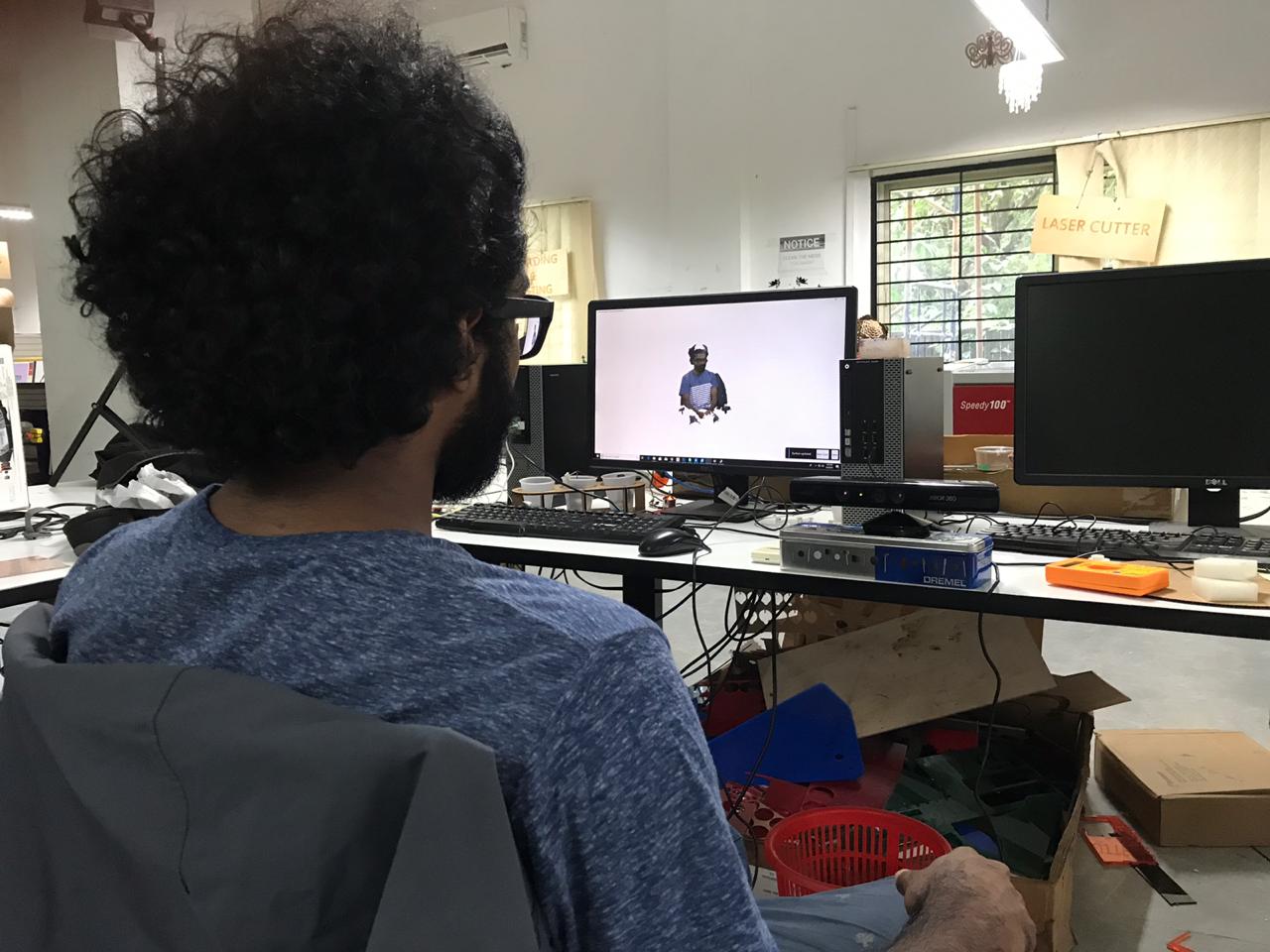
My friend akhil volantear for 3d scanning. I have used Re-Construct Me . I started a new scan and select Kinect as input device.
So I started my scaning and I got following result.
Now I have to save it. So I save it in my repo as an .stl file.
You can download the file here.